Solder
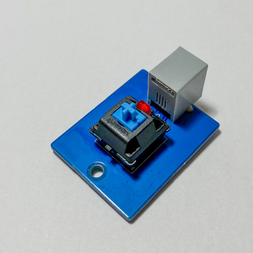
Solder the parts to the PCB in the following order:
- Cherry MX switch.
- The LED. There should be an indent on the keyswitch for it.
- RJ10 socket.
Tips:
- All parts go onto the same side of the PCB, the one that has component names and outlines.
- Double-check that the switch is aligned with the outline printed on the PCB.
- Make sure to solder the LED the right way around. The long lead is the anode (+). There’s a handy drawing printed on the PCB.
Also see the general information on soldering.
The end result should look like this:

Next up you’ll need to print an enclosure.